| Items |

S-RT440-0ZI
All Metal, RT® Free-Running Locknuts - Unified
|

S-RT632-0ZI
All Metal, RT® Free-Running Locknuts - Unified
|

S-RT832-0ZI
All Metal, RT® Free-Running Locknuts - Unified
|

SS-RT032-0ZI
All Metal, RT® Free-Running Locknuts - Unified
|

S-RT0420-0ZI
All Metal, RT® Free-Running Locknuts - Unified
|
|
Description
|
N/A
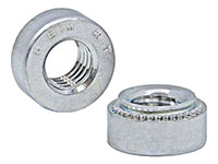
PEM® S-RT™ free-running locknuts are free-running until clamp load is induced. A modified thread angle on the loaded flank provides the vibration resistant locking feature.
- Screw turns freely until a clamp load is applied.
- Resistant to vibrational loosening.
- Back side of panel is flush or sub-flush for screw installation.
- Locking feature reusability is not affected by number of on/off cycles.
- Uses same mounting hole and installation tooling as standard S™ nut fasteners
found in PEM® Bulletin CL.
|
|
Thread Size
|
N/A
.112-40 (#4-40)
|
N/A
.138-32 (#6-32)
|
N/A
.164-32 (#8-32)
|
N/A
.190-32 (#10-32)
|
N/A
.250-20 (1/4-20)
|
|
Thread Code
|
N/A
RT440
|
N/A
RT632
|
N/A
RT832
|
N/A
RT032
|
N/A
RT0420
|
|
Shank Code
|
N/A
0
|
|
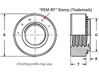
A (Shank) Max.
|
N/A
.030 in

|
N/A
.030 in

|
N/A
.030 in

|
N/A
.030 in

|
N/A
.045 in

|
|
Rec. Min. Sheet Thickness1
|
N/A
.030 in
|
N/A
.030 in
|
N/A
.030 in
|
N/A
.030 in
|
N/A
.047 in
|
|
Hole Size in Sheet + .003 - .000
|
N/A
.166 in
|
N/A
.1875 in
|
N/A
.213 in
|
N/A
.250 in
|
N/A
.344 in
|
|
C Max.
|
N/A
.165 in
|
N/A
.187 in
|
N/A
.212 in
|
N/A
.249 in
|
N/A
.343 in
|
|
E ± .010
|
N/A
.250 in
|
N/A
.280 in
|
N/A
.310 in
|
N/A
.340 in
|
N/A
.440 in
|
|
T ± .010
|
N/A
.070 in
|
N/A
.070 in
|
N/A
.090 in
|
N/A
.090 in
|
N/A
.170 in
|
|
Min. Dist. Hole C/L to Edge
|
N/A
.19 in
|
N/A
.22 in
|
N/A
.27 in
|
N/A
.28 in
|
N/A
.34 in
|
|
For Use in Sheet Hardness
|
N/A
HRB 80 / HB 150 or Less
|
|
Thread Specification
|
N/A
Modified thread form on loaded flank. Will accept a maximum material 6g screw.
|
|
Fastener Material
|
N/A
Hardened Carbon Steel
|
|
Standard Finish
|
N/A
Zinc plated per ASTM B633, SC1 (5µm), Type III, colorless
|
|
Optional Finish
|
N/A
|
|
CAD Supplier
|
N/A
PennEngineering® (PEM®)
|


